With the rapid development of the automotive industry, long glass fiber reinforced thermoplastic composites (LGF) have been increasingly applied.
Under the trend of automotive lightweighting, “replacing steel with plastics” has become a mainstream approach. By taking full advantage of LGF’s low linear expansion coefficient, high specific strength, high specific modulus, and excellent dimensional stability, its application in lightweight automotive structures effectively reduces vehicle weight, enhances power performance and handling, lowers energy consumption, and improves driving range.
Performance Analysis
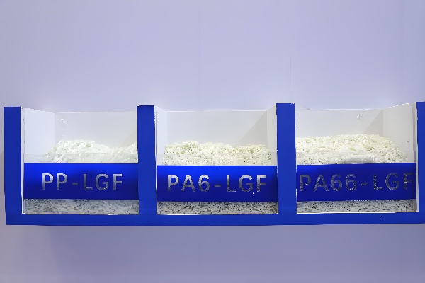
1.1 Flame‑Retardant PP‑LGF Materials
Long glass fiber reinforced polypropylene (PP‑LGF) materials offer excellent mechanical properties and dimensional stability, making them widely used across various industrial fields. They can also be designed to exhibit intumescent flame‑retardant or synergistic flame‑retardant performance. These materials are mainly classified into two flame‑retardant types: nitrogen‑phosphorus based and bromine‑based.
The nitrogen‑phosphorus system forms a porous, expanded char layer on the surface of the PP matrix through the action of flame retardants. This char layer acts as a thermal and oxygen barrier, improving the strength and heat resistance of the char, effectively delaying the decomposition and oxidation of the matrix resin, and enhancing the overall flame‑retardant performance of the composite system, thereby achieving flame retardancy for the matrix resin.
Bromine‑based flame retardants primarily rely on the bromine–antimony synergistic effect. During thermal decomposition, they generate inert substances that slow down or terminate combustion. Additionally, the dense HBr produced can dilute oxygen in the surrounding air, is non‑flammable, and can form a protective layer on the material surface to inhibit burning, reduce the combustion rate, or promote self‑extinguishing.
The properties of some typical flame‑retardant PP‑LGF materials currently used in applications are summarized in Table 1.
Table 1 Performance of Flame‑Retardant PP‑LGF Materials
|
Property
|
PP‑LGF20 (Nitrogen‑Phosphorus)
|
PP‑LGF20 (Bromine‑Based)
|
|
Glass Fiber Content / %
|
20
|
20
|
|
Tensile Strength / MPa
|
94.8
|
87.6
|
|
Flexural Strength / MPa
|
149
|
132
|
|
Flexural Modulus / MPa
|
5540
|
5620
|
|
Notched Impact / kJ/m²
|
20
|
17
|
|
Unnotched Impact / kJ/m²
|
45
|
41
|
|
Flame Retardancy (3.2 mm)
|
V-0
|
V-0
|
From Table 1, it can be seen that flame-retardant PP-LGF materials, while maintaining good synergistic flame-retardant performance, also retain considerable mechanical properties including tensile strength, flexural strength, and notched impact strength.
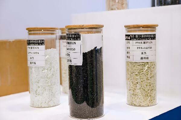
1.2 PA66-LGF Materials
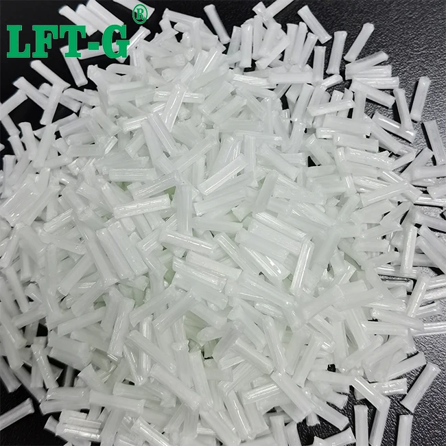
PA66-LGF materials are reinforced composites with high heat resistance, high strength, high modulus, and excellent toughness. Among them, PA66-LGF30 contains 30% long glass fiber reinforcement, while PA66-LGF25 contains 25%. Both are produced in pellet form, which significantly enhances the mechanical strength and dimensional stability of the material, providing outstanding impact resistance. The properties of typical PA66-LGF materials are shown in Table 2.
Table 1 Performance of Flame‑Retardant PP‑LGF Materials
|
Property
|
PA66-LGF30
|
PA66-LGF25
|
|
Glass Fiber Content / %
|
30
|
25
|
|
Tensile Strength / MPa
|
170
|
151
|
|
Flexural Strength / MPa
|
228
|
208
|
|
Flexural Modulus / MPa
|
8050
|
7720
|
|
Notched Impact / kJ/m²
|
21
|
18
|
|
Unnotched Impact / kJ/m²
|
69
|
66
|
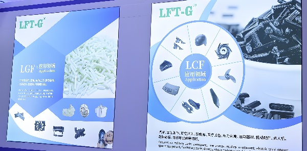
Applications
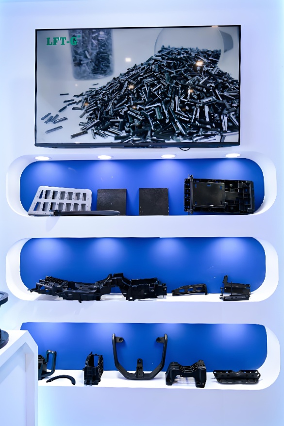
LGF is widely used in automobiles, aerospace, sports, household appliances, and packaging, with the automotive industry being the primary sector of application, accounting for about 80%.
2.1 Automotive Wheels
Nylon long glass fiber (LGF) is a high-temperature resistant, self-lubricating reinforced material capable of withstanding medium to high loads. As a material that perfectly combines long fiber reinforcement with lubrication, it can operate under conditions of up to 130 °C. With good versatility, it is suitable for dry running applications, primarily used in rotational and sliding motions, featuring excellent dust resistance and requiring no maintenance.
In automotive lightweight design and development, long glass fiber reinforced PA66 materials are well suited for automotive wheel components, enabling the production of composite plates and passenger car wheels through injection molding.
The preparation method for composite plates involves drying the pellets at 100 °C for 4 hours, followed by injection molding. The molding process parameters—such as screw temperature, screw pressure, injection pressure, injection time, back pressure, cooling time, and mold temperature—are set accordingly. After molding, the plates are cooled in air to room temperature.
The preparation of composite wheels follows a similar process: pellets are dried at 100 °C for 4 hours and then injection-molded. Process parameters include hot runner temperature, injection pressure, injection time, holding pressure, holding time, cooling time, and mold temperature. The final product is a 15-inch composite wheel.
Subsequent testing and analysis of the plates and wheels determine the glass fiber content, fiber length, orientation, and distribution. Radial fatigue tests on the composite wheels further confirm their fatigue resistance performance.
2.2 Engine Hood Cover
Considering the high specific strength, specific modulus, and impact resistance of long glass fiber reinforced polypropylene (PP-LGF), it can be effectively applied in automotive engine hood components. By optimizing mold design and adjusting processing parameters, parts that meet both appearance and performance requirements can be manufactured, thereby fulfilling the needs of lightweight automotive applications while minimizing costs.
Based on the performance requirements of engine hood covers, PP-LGF30 was selected. Through trial production and performance verification, it was found that the material’s tensile strength, flexural modulus, notched impact strength, and heat deflection temperature meet the functional requirements of engine hood applications. To further optimize the appearance quality of PP-LGF30 parts, adjustments in mold design and processing are necessary. For example, venting holes can be added at the melt flow ends to address molding difficulties, and a mold temperature controller can be used to maintain the mold temperature at 80 °C.
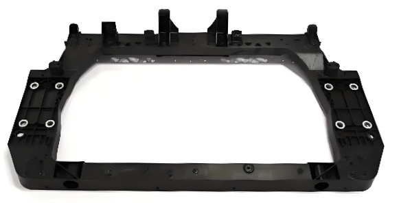
2.3 Front-End Module
In the development of automotive lightweight design, long glass fiber reinforced polypropylene (PP-LGF), with its excellent mechanical properties, can be applied to automotive front-end frames. By reasonably incorporating structural topology optimization, dimensional optimization, and other design techniques, and based on the development of modified PP-LGF materials, optimized formulations and raw material selection can be achieved, followed by experimental compounding, testing, and process design.
The process mainly includes:
① Raw material inspection – focusing on appearance standards, moisture content, black particle count, and melt flow rate.
② Process control – conducting online ash content testing, with inspections performed every 2 hours.
③ Finished product inspection – examining product appearance, color, ash content after burning, density, melting temperature, flexural strength, flexural modulus, notched impact strength, and overall impact resistance.
2.4 Front Hood
In the process of automotive lightweight design, the concept of “replacing steel with plastics” has been increasingly recognized. The front hood of vehicles is now being manufactured using long glass fiber reinforced plastic composites, which are lighter in weight and offer superior performance, thereby effectively reducing overall vehicle mass and meeting energy-saving and emission-reduction requirements.
During the improvement and optimization of the front hood structure, long glass fiber reinforced composites are used to replace the original metal materials. Based on the mechanical properties of these composites, the equivalent design method is applied to redesign the hood structure, taking into full consideration factors such as elastic modulus, Poisson’s ratio, and thin-wall thickness to determine the initial thickness of the hood.
Further structural optimizations include: designing recessed platforms and cross ribs in the inner panel as reinforcement structures; adding small holes at the lower edge of the inner panel; adopting high-adhesion joining methods for hood assembly; and simplifying the sectional structure of the hood sides by using adhesive side seals.
2.5 Instrument Panel Skeleton
As a lightweight and high-strength composite plastic material, long glass fiber reinforced polypropylene (PP-LGF) can be applied in the automotive instrument panel skeleton. Leveraging its excellent mechanical properties and good environmental adaptability, PP-LGF is produced through the melt impregnation method, making it suitable for high-performance structural components such as instrument panels. The instrument panel is a critical part of the vehicle interior, requiring high strength and rigidity.
To reduce the weight of the instrument panel skeleton and promote lightweight interior design, PP-LGF materials with higher strength, superior flexural modulus, and better flowability should be selected. Under equivalent strength conditions, the design thickness of the instrument panel can be appropriately reduced, resulting in an approximate 20% weight reduction. Moreover, the traditional multi-component instrument panel support can be developed into a single integrated module, where the defrost air duct body and central skeleton are typically manufactured using the same material, thereby effectively achieving lightweighting requirements.
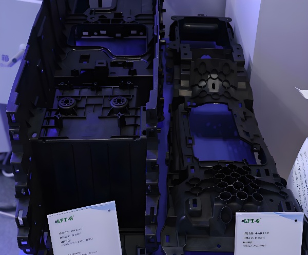
2.6 Battery Tray
Long glass fiber reinforced composites can be manufactured into complex-shaped components through injection molding. In meeting the lightweighting requirements of automotive battery trays, PP-LGF40 is selected due to its superior performance in reducing vehicle vibration and noise as well as improving corrosion resistance. The material can be molded into parts with complex structures and thin walls, while structural ribs are incorporated into the design to enhance stiffness. During production, corner transitions should be chamfered to reduce stress concentration and ensure the required rigidity of the battery tray.
Considering that installation holes and side flanges are subject to higher stresses than other regions, the wall thickness of the mounting holes should be appropriately increased, with ribs extending to the tray surface to strengthen these areas. To further improve the rigidity of the tray sidewalls, a 2 mm flange should be added along the sides and perimeter, and a grid-like rib structure (“井” shape) should be placed on the backside of the tray. In addition, pre-deformation adjustments should be made to account for rib-induced warpage, ensuring both assembly compatibility and enhanced stiffness, thereby meeting automotive lightweighting requirements.
2.7 Tailgate
Plastic tailgates can be manufactured using long glass fiber reinforced polypropylene (PP-LGF) thermoplastic composites, which offer low density, high strength, high recyclability, and design flexibility. This material significantly reduces fuel consumption and CO₂ emissions while enabling greater component integration. In PP-LGF tailgate design, both the inner and outer panels are produced via injection molding, with adhesive bonding between them. Simulation analysis is performed to optimize structural integrity and performance.
The inner panel, which bears most of the load, must be reinforced with ribs at the upper section and the D-pillar regions to ensure sufficient strength and stiffness. During material selection, the coefficient of linear thermal expansion of the inner and outer panels must be carefully matched, particularly under alternating hot and cold conditions. Poor matching may result in debonding or deformation of adhesive joints due to thermal expansion and contraction.
2.8 Fender
Using specialized molding equipment, PP-LGF granules with a specified glass fiber content are prepared and applied in automotive fender structures. When designing fenders with PP-LGF, it is essential to evaluate the influence of glass fiber content on tensile, flexural, and impact properties through performance testing.
Non-mechanical properties must also be assessed, including resistance to high temperature, thermal cycling, impact, damp heat, water, and solvents. Observations should be made for potential defects such as deformation, cracking, chalking, bubbling, stickiness, or dissolution. Following testing, the fender components are assembled to validate their suitability for different operating conditions and ensure compliance with lightweighting and durability requirements.
Conclusion
In summary, long glass fiber reinforced composites are high-strength and lightweight materials. Against the backdrop of “replacing steel with plastics,” they demonstrate distinct performance advantages and are well-suited for application in automotive lightweight structural design.